 pdf version of this document
the Harmonii Computer
Vision Environment
Harmonii is
a software environment for developing computer vision applications, primarily
aimed at autonomous vehicles and Driver Support Systems (DSS). The software
consists of a pipeline of image processing operations that progressively produce more and more sophisticated
models of the image and of the outside world it captures. It integrates a
number of powerful techniques for image understanding, including stereo (depth)
vision, segmentation and linear feature discovery. Furthermore, it builds a 3D
model of the visual features produced, and plans trajectories for mobile robots
and autonomous vehicles based on the modelled obstacles.
The system
contains a graphical user interface for experimenting with the different
modules, finding the optimal settings for parameters in analysing in detail the
effects of the processing. As such, it also serves as a test-bed for those
interested in learning about important techniques in the Computer Vision field.
Alternatively, the system can be integrated in real-time applications requiring
a vision or motion planning component, through its Java-based API.
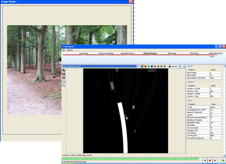
The Harmonii graphical user interface
Some of the
implemented operations, notably stereo vision, require considerable
computational resources. These operations have been made efficient in two ways.
First of all, key algorithms have been made multi-threaded in order to benefit
from multi-processor or multi-core hardware. A typical run of the complete
pipeline, leading to a planned path, can be perform up to twice a second, given
the right parameter settings. A further improvement has been obtained by
re-implementing some parts for computation on a Graphics Processing Unit (GPU).
On a modestly-priced graphics card, this hardware-acceleration will result in a
speed-up of 10 times.
The name
Harmonii is inspired by the term harmony in music: the effects of notes
sounding simultaneously. The software exploits the effects of combining
multiple (stereo-) images captured simultaneously. Analogously, work continues
on the Symphonii component, which adds to this the possibilities of combining
successive images.
The
following sections describe some of the main features of Harmonii. For detailed
information and pricing, please contact {a dot knobbe at this domain}.
Image Processing
A number of
basic operations is available for turning the original colour image(s) into a
range of images suitable for further processing.
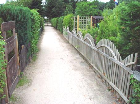
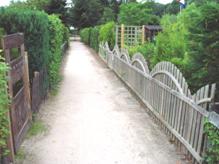
Original colour image
The
pipeline starts by separating the original images into each of the three RGB
components as well as a grey-scale component. Furthermore, channels for the hue,
saturation and brightness (HSB) colour-model are added.

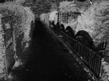
Grey
component
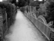
Saturation component
Each of
these 7 channels can optionally be complemented with blurred versions. A range
of kernel functions can be used to smooth the original image, for example to
remove any noise in the image. Additionally, this blurring has the effect of
gathering information about neighbouring pixels in each pixel, which is useful in
subsequent steps. Also, a number of edge detection kernels can be applied in
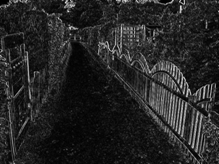
order to gather information about strong changes in intensity in the images.
This can be used to detect lines or road markings in the image. Again this
operation can be applied to all of the channels.
Blurred
grey
Edge detected grey (Sobel)
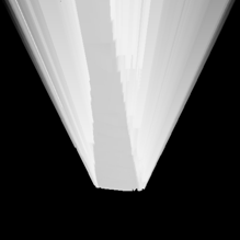
Stereo Vision
The most
important technique for image understanding in Harmonii is the stereo vision
module. By comparing two images taken by two identical cameras situated next to
one another, it is possible to gage the depth of objects appearing in the two
images. For each pixel in the left image, a corresponding pixel in the right
image is determined. The so-called disparity
between these pixels is a measure for the distance of the object from the
camera-pair. Finding the correct corresponding pixel is done by comparing the
neighbourhood of the pixel. This can be done based on any subset of the
channels available, although typically just grey (and/or green) is a reasonable
and efficient choice. Optionally the blurred and edge detected images may
provide additional information that can help improve the estimated depth,
especially in areas where neighbouring pixels are similar.
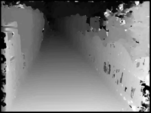
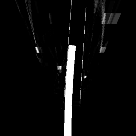
Original image (left version) Depth map (dark =
deep)
By
measuring the depth of each pixel, the outside world can now be modelled using
a cloud of dots in 3D. This cloud can arbitrarily be translated and rotated to
compensate for unusual mounting or tilting of the cameras on the robot. By
bounding the cloud, objects that are not relevant to navigation (such as ground
or overhead obstacles) can be filtered out. The cloud can be visualised in a
number of ways. A density map projects all dots on a horizontal surface, thus
showing where obstacles appear in the area in front of the cameras. A height
map shows the height of obstacles for this same area.
Density map 15m ahead Height map for the same area
Motion Planning
The 3D
model of the outside world can be used to plan paths for the mobile robot the
cameras are attached to. Harmonii considers a number of possible paths and
selects the path with the lowest risk, based either on density or height of the
obstacles. A range of parameters can be used to model the properties of the
robot, such as its size and maximum steering angle, and the planning distance.
Relevant obstacles Minimum risk path based on density
The system
contains minimal facilities for interfacing with electronic interface cards
that drive external motors. It assumes that steering is done differentially,
that is by controlling the difference in speed between the left and right
wheels. Using the API, the vision and motion planning functionality can of
course be integrated in operational systems of any complexity.
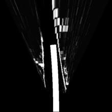
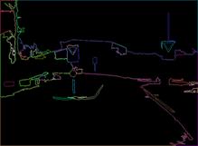
Discovering linear features
In many
applications, planning a path requires more than simply avoiding obstacles. For
example on a highway, it can be more important to keep to the current lane,
than to avoid obstacles. Harmonii provides facilities for recognizing linear
features such as the side of the road and road markings (even interrupted). A
so-called Hough transform produces
these linear features (see figure). The horizontal line indicates the location
of the horizon. Its width indicates that only lines will be found that point
roughly in the viewing direction. There is a further limit on the slope of the
line in the 2D image.
Two lines discovered in the horizontal plane
Using the
3D model of the scene that was created from the stereo images, the 2D lines can
be translated to lines in the outside world. Any lines that do not turn out to
be straight in 3D, or do not lie in the horizontal plane (within limits) are
discarded.
The motion
planning module can benefit from this additional information by combining
obstacles and lines into a single map of the outside world. The figure below
shows how the optimal path falls between the two parallel lines discovered. The
positions of the two poles and the tree are indicated, as well as the two
lines. Clearly, just navigating based on obstacles would result in a less
attractive path.
Path that respects both density and lines
Segmenting images
Smooth
surfaces, such as paved roads, present some challenges to stereo vision, as it
is harder to determine corresponding pixels when all pixels are equal. Small
imperfections and dirt will help to resolve some of these. The smoothness of
flat areas however can also be exploited. A simple way of recognizing how the
road continues ahead (when straight lines are not present), is to assume that the
area directly in front of the robot is safe. By extending this area to include
all similar pixels, it is possible to determine where the road continues to.
Harmonii offers techniques for segmenting images and thus determining areas
with similar properties. For the recognition of road and flat, smooth surfaces,
using saturation as a means of determining similar areas is useful, because it
is not sensitive to variation in lighting and shadows (see figure below). The
system however allows you to pick any of the available channels.

Segmented image with polygons. The black area corresponds to road
surface.